How to Calculate Pump Head: A Practical Guide for Homeowners
The visible pump is only one part of this job. A successful result depends on the source, pipe or tubing, controls, power, and the conditions at the outlet, so document that arrangement before making the first change.
What you need for this job
- the exact model manual
- appropriate tools and approved replacement parts
- power and pressure isolation
- a clean, dry work area
- a way to observe flow, head, or the control cycle
Before touching the pump
Turn off and verify the relevant power, isolate water or pressure, and identify any automatic switch, controller, alarm, or timer that could start the pump. Keep sewage, septic tanks, wet electrical connections, pressure vessels, and confined spaces outside casual DIY work.
Details that decide whether the job will work
Decide whether you need head or pressure
Head describes the energy required to move a liquid, while pressure is a force reading at a point. For water, 1 PSI is approximately 2.31 feet of head, but the conversion does not eliminate friction or flow dependence.
Set the target flow first
A head calculation without a flow rate is incomplete because friction changes with flow. Use fixture demand, irrigation-zone output, measured transfer rate, or the feature requirement that the pump must actually deliver.
Measure the correct elevation
Use the source water level or pumping level and the endpoint, not simply the height of a tank or building. In a balanced closed loop, static elevation may cancel while equipment and pipe losses remain.
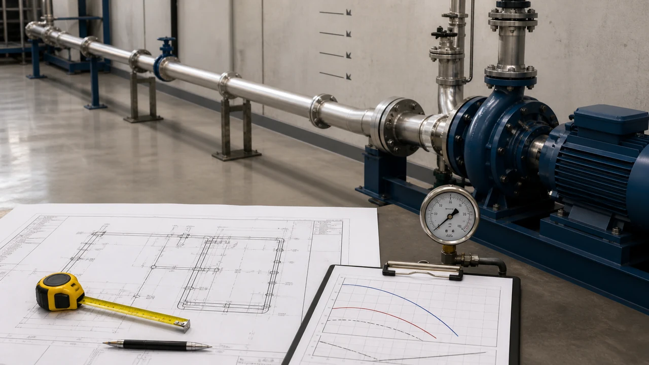
Add resistance from the whole route
Include pipe length, diameter, material, fittings, valves, filters, check valves, nozzles, and any required endpoint pressure. Do not turn a long small hose into a negligible detail.
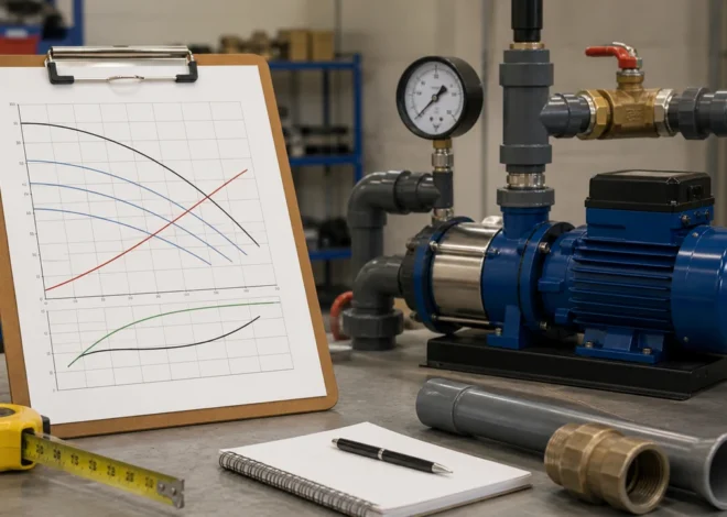
Read the pump curve at the result
Mark the required flow and calculated head on the correct curve for the model, speed, impeller, liquid, and voltage. Maximum head is usually a zero-flow limit, not the flow available at that height.
Check the range of conditions
Recalculate if source level, filter condition, demand, or speed changes. A selection that works at one operating point may stall or overload at the high-resistance end of the system.
Step-by-step procedure
Identify the system
Confirm pump type, liquid, source, endpoint, and control arrangement.
Make it safe
Turn off and verify power, relieve pressure, and keep water away from electrical connections.
Document the starting arrangement
Photograph pipes, wires, valves, and settings before disconnecting anything.
Perform the service
Follow the model-specific sequence and do not force fittings or bypass controls.
Reassemble
Use correct seals, pipe sizes, fasteners, and wiring.
Test gradually
Observe flow, head, leaks, sound, temperature, and control behavior.
The measurements to gather before starting
Write down the source level, endpoint, required flow, vertical rise, pipe or hose size, length, fittings, valves, filters, and any pressure that must remain at the outlet. This record prevents a pump procedure from being judged against a different installation than the one that will actually run.
Separate static conditions from operating conditions
A closed gauge, empty hose, or still water level is only a starting observation. Flow creates friction, a well level can fall while pumping, a filter can load with debris, and a pressure system can lose inlet pressure as demand opens. Use measurements taken under the condition the pump must handle.
Use the correct model information
Nearby versions can use different impellers, speeds, voltage, controls, or connection sizes. Match the model number and curve to the pump in front of you. A generic curve or a product-page maximum may not describe the installed configuration.
Know when a number is an endpoint
Maximum flow is usually shown near zero head, while shutoff head is shown near zero flow. Neither is the normal operating point. The useful result is the flow where the system head and the correct pump curve intersect.
Check the result against the system
After the calculation or priming step, verify that the source remains adequate, the pump stays inside its temperature and duty limits, and the outlet carries the expected flow. If the pump only works with a valve in an unusual position or a control bypassed, the job is not complete.
If the finished job behaves differently
The motor runs but output is poor
Check source level, inlet restriction, prime, pipe or hose size, vertical rise, filters, valves, and the endpoint. Compare the actual route with the model curve before replacing the pump.
The pump starts and stops unexpectedly
A float, pressure switch, controller, timer, thermal protector, low-water sensor, or leak may be controlling the cycle. Record the timing and condition instead of bypassing protection.
The pump becomes hot or noisy
Dry running, air, cavitation, debris, vibration, overload, and worn parts can overlap in sound. Stop the test if heat or severe noise appears and use the exact manual for service limits.
The first repair does not hold
A recurring symptom often lives in the source, pipe, controls, liquid, or duty rather than the replaced component. Save the before-and-after observations and have the complete system reviewed.
How to verify the result
The system completes a normal cycle, delivers water or air as intended, and does not leak, overheat, or trip protection.
If the procedure does not work
Stop rather than repeating the same start-up cycle. Recheck the model, source, valve positions, pipe or tubing, control signal, and actual head. If the next check involves live wiring, a sealed system, sewage, a well, or a buried line, arrange qualified service.
Common mistakes after the main job is finished
- Leaving a temporary hose, bypass, jumper, or extension cord in a permanent installation.
- Closing a valve or filter path that the pump needs for cooling or flow.
- Hiding the float, alarm, controller, cleanout, or service connection behind a finished surface.
- Testing only at zero demand instead of under the flow or pressure the system must deliver.
- Changing a switch, fuse, pressure setting, or controller parameter without checking the exact manual.
- Forgetting to inspect for leaks, backflow, air, vibration, heat, or abnormal cycling after shutdown.
Keep the repair from becoming the next failure
Leave the pump, switch, valve, cleanout, and connection points accessible. Record the normal pressure, flow, water level, runtime, or cycle behavior so a future change can be recognized early.
A useful handoff record
| Record | Why it helps |
|---|---|
| Exact model and settings | Prevents a future replacement or adjustment from being based on a similar-looking unit |
| Normal operating point | Provides a reference for pressure, flow, water level, or runtime |
| Connection and valve arrangement | Shows how the source, pump, controls, and endpoint are meant to work together |
| Date and service performed | Makes recurring faults and maintenance intervals easier to identify |
Frequently Asked Questions
Can I use a generic replacement part?
Only when the manufacturer or a qualified supplier identifies it as compatible with the exact model. Similar dimensions do not guarantee correct operation.
Why should power be isolated?
Pumps can start automatically through a float, pressure switch, timer, or controller. Isolation prevents unexpected movement and electrical contact.
What if the pump still fails?
Stop and compare the result with the manual’s troubleshooting sequence. A source, pipe, control, or endpoint problem may remain.
Should I test under full demand?
Use the controlled test stated by the manual, then verify the actual operating condition. Do not create a hazardous pressure or flow condition just to test capacity.
When is professional service needed?
Use it for live wiring, wells, sewage, pressure vessels, buried lines, pool suction, or any task the manual reserves for qualified personnel.
Bottom line: The procedure is complete only when the pump performs a normal, controlled cycle and the surrounding system remains safe. Use the exact manual for details that this general guide cannot establish.